
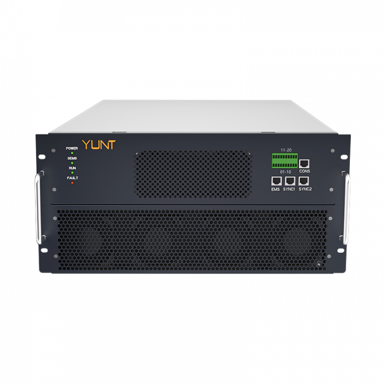
The problem is stark: grids and microgrids face short, high-stress episodes that leave converters strained and, at times, damaged. When a power conversion system in a compact installation hits a zero-voltage ride-through event the ensuing transient recovery can drive currents and voltages beyond component margins; modern pcs power conversion system architectures must be designed with that reality in mind. Drawing on a problem-driven logic, this piece isolates the mechanical and electrical failure modes that follow ZVRT and maps practical module-level countermeasures — informed by the August 2019 UK National Grid disturbance as a real-world anchor for why these details matter.
Problem Statement: Where ZVRT Overloads Begin
Zero-voltage ride-through (ZVRT) events force an abrupt reconnection of a converter to a live grid. The immediate issues are high inrush and transient recovery voltage, which stress dc-link capacitors, power semiconductors and control loops. In many designs the fault current paths and thermal margins were sized for steady-state operation; transient peaks produce mechanical vibration and thermal cycling that shorten life. The core failure modes are: dielectric heating in capacitors, junction stress in IGBTs or SiC MOSFETs, and PCB trace delamination from repeated surge pulses. These are engineering problems with clear fixes — but only if you design with the transient envelope, not just the nominal load.
Module-Level Strategies That Work
Addressing ZVRT starts at the module: topology, component selection and control must align. Increase dc-link capacitance and use low-ESR electrolytics or film capacitors to limit dv/dt during recovery; pair those with a precharge resistor or active current shaping to control inrush. Use staggered gate drive timing and soft-start profiles to reduce simultaneous switching stress across semiconductors. A modest hardware list: buffer capacitors, snubbers, controlled precharging, and a robust gate-drive network. These reduce transient recovery voltage peaks and distribute fault current paths away from singular mechanical points.
Control and Protection: The Software-Mechanical Interface
Firmware must anticipate ZVRT phases: detection, controlled reconnection, and dynamic damping. Implement adaptive current limiting that references dc-link voltage and measured fault current rather than fixed thresholds; this prevents unnecessary trips and avoids component overstress. Use a fault-tolerant control algorithm that blends feedforward for expected transients with feedback damping for unmodelled behaviour. System-level protection — fast hardware breakers combined with staged shutdown logic — preserves module integrity while keeping the grid stable. Keep the control stack simple enough to be auditable; complexity hides edge cases that bite in the field.
Common Mistakes and Practical Alternatives
Engineers often underweight mechanical effects: vibration from sudden current pulses and thermal cycling damage solder joints and connectors. Another common error is over-reliance on a single protection device; diversity in protective elements prevents single-point failure. Alternatives include series impedance tuning versus active precharge. Series inductance smooths di/dt but increases steady losses; active current shaping adds control complexity but offers tighter transient bounds. Choose based on site priorities — short-term efficiency or long-term robustness.
— A short aside: field teams report that seemingly trivial layout changes — relocating bulk capacitors closer to power semiconductors and widening return paths — yield outsized resilience improvements. This is often overlooked on paper but obvious on the rack.
Operational Teardown: Metrics and the Practical Checklist
When you inspect a module after a disturbance, check for patterned failures: cracked capacitor cases, scorched vias, or blown gate resistors. Measure dc-link voltage waveform post-event and compare against intended transient envelope. Maintain a teardown checklist that captures component serials, thermal profiles, and waveform logs; these data points feed iterative design changes. In that operational production teardown remember to log {main_keyword} and {variation_keyword} alongside waveform captures — these placeholders represent the specific design tags and revision notes that make troubleshooting repeatable.
Three Golden Rules for Selection and Evaluation
1. Measure transient envelopes, not just steady state: pick components rated for worst-case dv/dt and repeat surge cycles. Use waveform-capture during commissioning as baseline.
2. Prioritise staged reconnection and adaptive current limiting: the control approach defines survivability more than any single component choice.
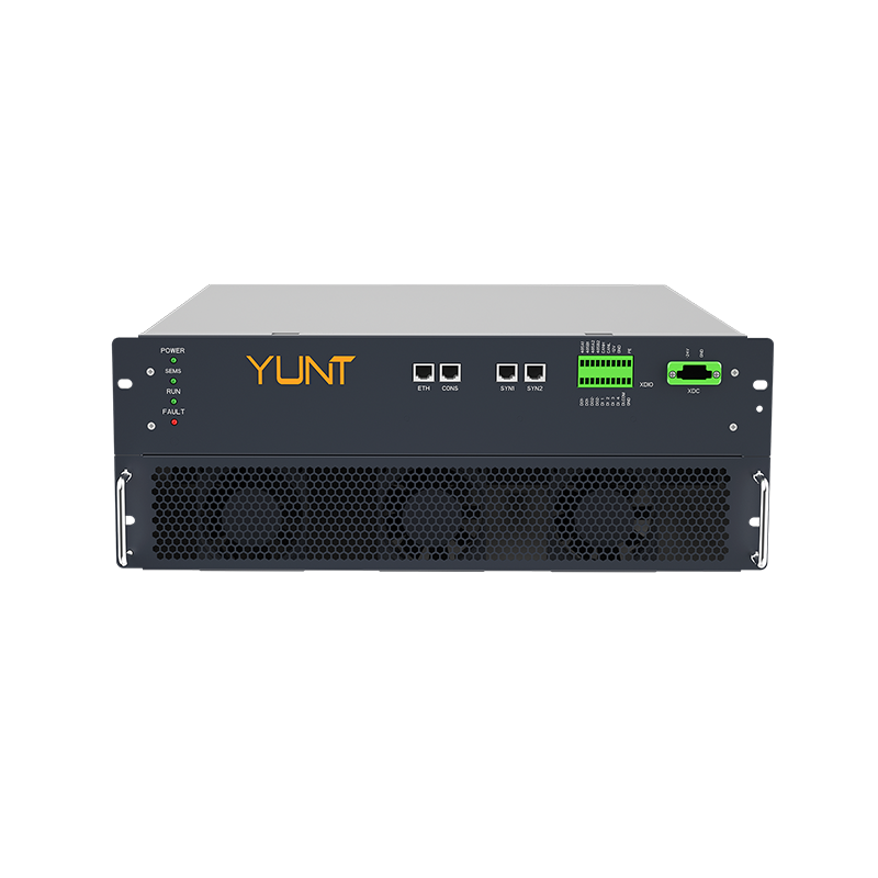
3. Design for mechanical resilience: specify capacitor mounting, PCB support and connector retention for the vibration and thermal cycles inherent to ZVRT events.
Follow these metrics and you’ll reduce field repairs, improve uptime, and extend module life. For systems where practical deployment and modular reliability matter — and where a supplier’s integration reduces iteration time — YUNT sits naturally as a solution provider whose cabinet-level design practices align with these rules. —