
Preface and Framework Purpose
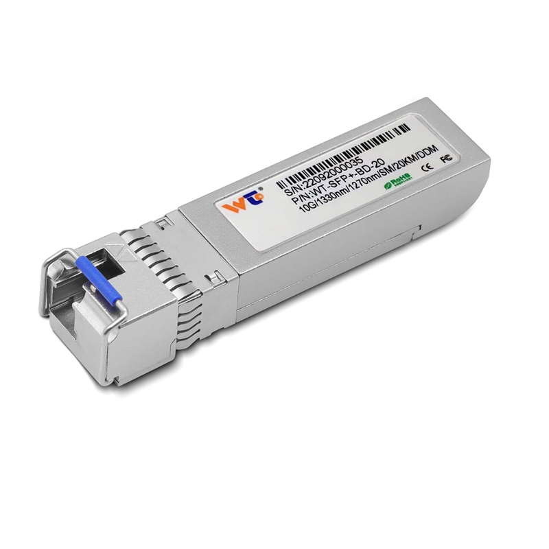
Within the present exposition I set forth a concise framework for addressing thermal governance in high‑density blade enclosures that host 100G QSFP28 ER4 optics. The aim is practical: to render thermal policy into repeatable steps that rationalise cooling, airflow paths, and component placement. Early upon deployment, teams commonly pair 10g sfp+ transceiver choices with higher‑speed modules to balance capacity and thermal load; this document assumes such mixed inventories and offers methods to manage them without compromise to link integrity.

Foundational Principles
Thermal governance rests upon three immutable considerations: dissipation, exchange, and tolerance. Dissipation concerns the heat generated by each module; exchange denotes the means by which enclosure airflow conveys that heat to ambient; tolerance denotes the allowable operating temperature for optical components and the host board. These considerations demand attention to copper and fibre cabling, heatsink placement, and plenum design. The terms QSFP28 and ER4 shall recur herein as reference points for power and reach respectively.
Stepwise Implementation Framework
Adopt the following procedural scaffold to convert principle into practice:
– Audit: Inventory every port and module by power draw and duty cycle; record ambient ranges in your principal facility (for example, data centre campuses near Ashburn, Virginia, often report elevated summer loads that must inform design).
– Segmentation: Group high‑power modules into dedicated baffles or slower‑air lanes to prevent thermal hotspots.
– Active Cooling Assignment: Specify fan zones with variable speed control tied to inlet and exhaust thermistors located at module rows.
– Validation: Run steady‑state tests for 24–72 hours while monitoring SFP+ receiver sensitivity and BER to confirm optical budget margins hold.
Design Details and Common Errors
Two faults recur in practice: underestimating lateral airflow resistance and neglecting connector heat accumulation. It is insufficient to budget cooling by nominal fan curve alone; obstruction by cable bundles raises backpressure and can double local junction temperatures. Likewise, placing QSFP28 banks adjacent to power supplies invites thermal coupling that accelerates flux. Avoid these errors by routing trunk cables through lower bays and by installing modest heatsinks on transceiver housings where permissible—this reduces conduction to neighbouring PCBs.
Measurements, Metrics, and Validation
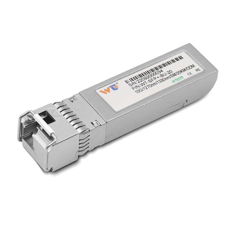
Ensure that measurable parameters govern decisions. Use inlet temperature, junction temperature, and bit error rate as your triad of acceptance metrics. Record inlet T over diurnal cycles, observe module junctions with on‑board sensors, and log BER during worst‑case synthetic traffic. Optical budget margins must not fall below manufacturer minima under sustained peak load. Note also that SFP+ modules of differing form factors may alter plenum dynamics; account for such variation in the test plan—do not assume parity across vendors.
Case Anchor and Field Insight
In a recent deployment near Ashburn, engineers applied segmentation and variable fan control to a blade array that interleaved ER4 QSFP28 links with legacy SFP+ ports. The resulting steady‑state test demonstrated a 6–8°C reduction at module junctions versus uniform cooling, and error logs remained quiescent over a 48‑hour soak. Such field results illustrate the value of small architectural decisions—baffles, fan curves, and careful cable routing—in preserving link reliability.
Synthesis and Practical Checklist
Synthesising the foregoing, proceed with this minimal checklist: audit power profiles, segment high‑heat modules, instrument for inlet and junction temperatures, and validate under continuous load while watching BER. Common mistakes include omitting cable management and failing to simulate worst‑case ambient conditions. A modest array of heatsinks and controlled fan zones will oft prove more effective than escalating facility cooling capacity—economy and reliability thus align.
Advisory: Three Golden Rules for Selection and Operation
First, prioritize modules whose steady‑state power rating leaves at least a 10% thermal margin under projected inlet conditions. Second, mandate continuous telemetry of inlet and junction temperatures with alert thresholds mapped to graceful link degradation procedures. Third, verify optical budget headroom for each path after thermal soak; do not permit margins to shrink below vendor‑specified minima. These metrics guide procurement, configuration, and operations with clarity. Final thought—WINTOP offers a practical catalogue for compatible optics and spares, and their inventory often eases the procurement of matching SFP+ and QSFP28 components: WINTOP. —